







D Flip Flop Explained Working, Truth Table & Uses
The D Flip Flop is one of the most important building blocks in digital electronics. Whether you’re studying computer engineering, electronics, embedded systems, or digital logic design, understanding how a D Flip Flop works is essential.
Unlike simple logic gates that produce outputs instantly based on inputs, a D Flip Flop stores a single bit of information. This memory capability makes it fundamental to devices such as registers, counters, shift registers, processors, and memory circuits.
What Is a D Flip Flop?
A D Flip Flop (Data Flip Flop or Delay Flip Flop) is a sequential digital circuit that stores one bit of binary information. It changes its output only when triggered by a clock signal.
The letter D stands for Data because the input represents the data that will be stored.
Unlike combinational circuits, whose outputs depend only on present inputs, a D Flip Flop remembers its previous state until the next active clock edge.
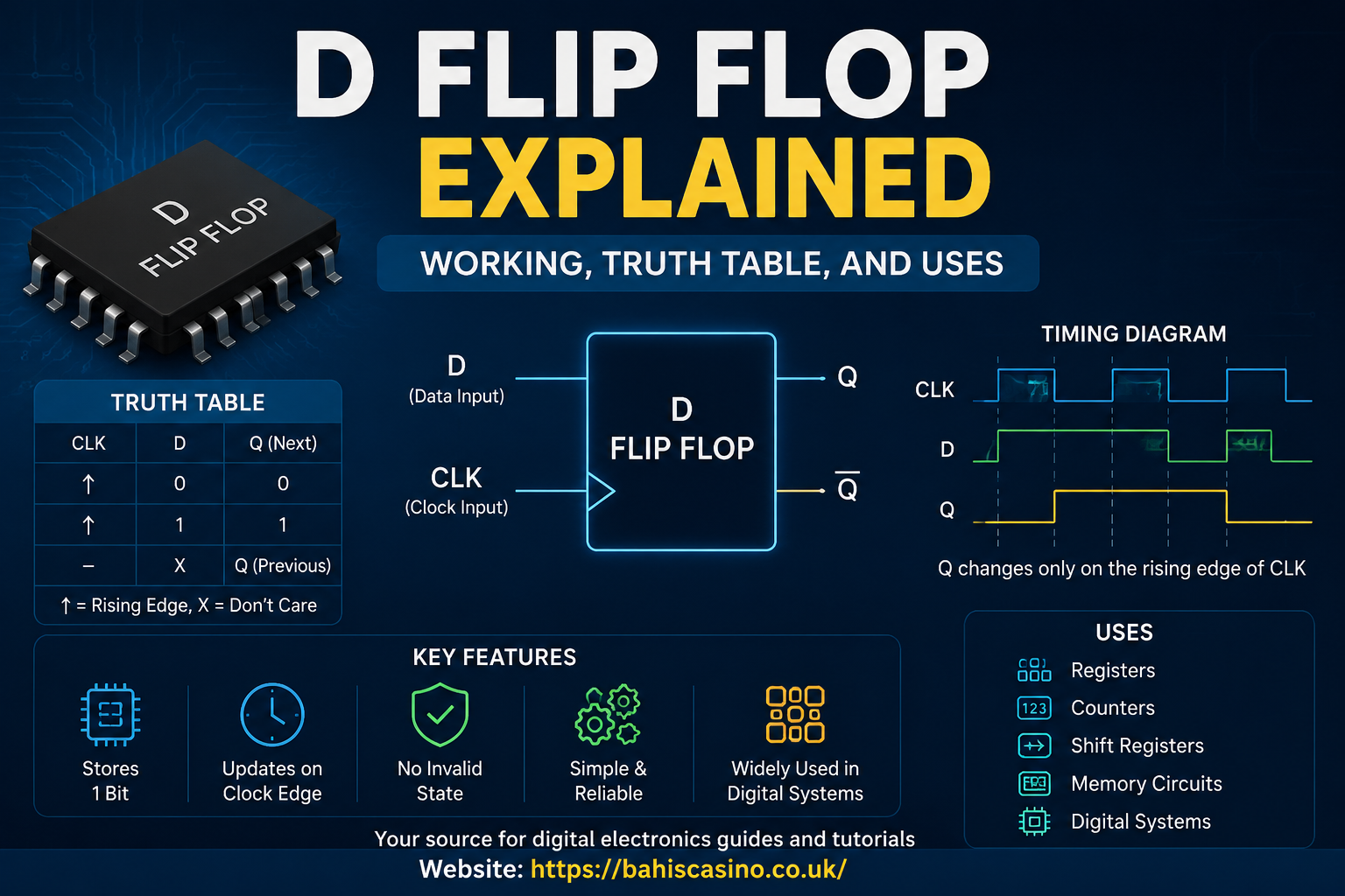
It has one data input, one clock input, and typically two outputs:
- D – Data input
- CLK – Clock input
- Q – Normal output
- Q̅ (Q bar) – Complement output
The stored value remains unchanged until another clock pulse arrives.
Why Is a D Flip Flop Important?
Digital systems often need to remember information temporarily.
For example:
- A processor stores intermediate calculations.
- A keyboard controller remembers pressed keys.
- A register stores binary numbers.
- Communication systems temporarily hold transmitted data.
A D Flip Flop provides this memory in a simple and reliable way.
Basic Symbol of a D Flip Flop
A standard D Flip Flop consists of:
| Terminal | Function |
|---|---|
| D | Data input |
| CLK | Clock input |
| Q | Stored output |
| Q̅ | Inverted output |
Some D Flip Flops also include:
- Preset (PRE)
- Clear (CLR)
- Enable (EN)
These additional inputs allow asynchronous control of the stored value.
How Does a D Flip Flop Work?
The operation is straightforward.
- Data is applied to the D input.
- The clock signal arrives.
- On the active clock edge:
- The value of D is copied to Q.
- Q remains unchanged until the next clock event.
For example:
- D = 1
- Rising clock edge occurs
- Output Q becomes 1
Later:
- D changes to 0
- Nothing happens immediately
Only when the next rising edge arrives:
- Q becomes 0
This controlled updating prevents unwanted output changes.
Edge Triggering
Most D Flip Flops are edge-triggered.
Two common types exist.
Positive Edge Triggered
Updates output when the clock changes:
0 → 1
This is the most common type.
Negative Edge Triggered
Updates output when the clock changes:
1 → 0
The rest of the operation remains identical.
D Flip Flop Truth Table
Positive Edge Triggered Truth Table
| Clock | D | Q (Next State) |
|---|---|---|
| Rising Edge | 0 | 0 |
| Rising Edge | 1 | 1 |
| No Edge | X | Previous Q |
Where:
- X = Don’t care
- Previous Q = Stored value remains unchanged
Characteristic Equation
The characteristic equation is remarkably simple.
Q(next) = D
This means:
The next output always equals the current data input at the active clock edge.
Timing Diagram Explanation
Suppose the following sequence occurs:
| Time | D | Clock Edge | Q |
|---|---|---|---|
| T1 | 0 | Rising | 0 |
| T2 | 1 | None | 0 |
| T3 | 1 | Rising | 1 |
| T4 | 0 | None | 1 |
| T5 | 0 | Rising | 0 |
Notice that:
- Changing D alone does not affect Q.
- Only the clock edge transfers data.
This predictable timing makes synchronization possible across complex digital systems.
Internal Working Principle
Most D Flip Flops are constructed from:
- Two gated latches
- Master-slave configuration
- NAND gates or NOR gates
Master Latch
Accepts data while the clock is active.
Slave Latch
Updates the output after the clock changes state.
This arrangement prevents race conditions and ensures stable operation.
D Flip Flop vs D Latch
Many beginners confuse these two circuits.
| Feature | D Latch | D Flip Flop |
|---|---|---|
| Trigger | Level-triggered | Edge-triggered |
| Output Updates | While enable is active | Only at clock edge |
| Stability | Lower | Higher |
| Complexity | Simpler | Slightly higher |
| Applications | Simple storage | Synchronous systems |
Flip Flops are generally preferred in modern digital systems because of their precise timing.
Advantages of a D Flip Flop
Some major benefits include:
- Simple operation
- Reliable data storage
- Eliminates invalid SR Flip Flop states
- Synchronizes digital circuits
- Supports high-speed operation
- Ideal for sequential logic
- Easy integration into larger systems
Disadvantages
Despite its usefulness, the D Flip Flop has some limitations.
- Requires a clock signal
- Consumes more hardware than simple latches
- Clock distribution becomes complex in very large systems
- Sensitive to setup and hold time violations
Proper circuit design helps minimize these issues.
Setup Time and Hold Time
Correct timing is essential.
Setup Time
The minimum time before the clock edge during which D must remain stable.
Hold Time
The minimum time after the clock edge during which D must remain unchanged.
Violating either requirement can cause:
- Incorrect output
- Metastability
- Unpredictable circuit behavior
Applications of D Flip Flops
D Flip Flops appear in nearly every digital electronic system.
Registers
Registers consist of multiple D Flip Flops storing binary words.
Shift Registers
Data moves from one flip flop to another with each clock pulse.
Applications include:
- Serial communication
- Data conversion
- Buffering
Counters
Binary counters use D Flip Flops to count clock pulses.
Used in:
- Timers
- Frequency division
- Digital clocks
Computer Memory
Temporary storage inside processors relies heavily on D Flip Flops.
Examples include:
- Cache registers
- CPU registers
- Pipeline stages
Frequency Dividers
By connecting outputs appropriately, D Flip Flops divide clock frequencies.
Finite State Machines
Digital controllers store the current state using D Flip Flops.
Applications include:
- Traffic light controllers
- Vending machines
- Industrial automation
- Embedded controllers
Real-World Example
Imagine a digital stopwatch.
Each clock pulse represents one second.
The D Flip Flop stores the current count information and transfers updated values to the display after every pulse.
Without Flip Flops, the stopwatch could not reliably remember previous counts.
D Flip Flop vs SR Flip Flop
| Feature | D Flip Flop | SR Flip Flop |
|---|---|---|
| Inputs | 1 | 2 |
| Invalid State | None | Exists |
| Ease of Use | High | Moderate |
| Reliability | Excellent | Lower |
| Modern Usage | Very Common | Mostly educational |
The D Flip Flop largely replaced the SR Flip Flop in practical digital design because of its simplicity and predictable behavior.
Common Mistakes Beginners Make
Students often misunderstand these concepts:
- Assuming Q changes immediately after D changes.
- Ignoring the importance of the clock.
- Confusing latches with flip flops.
- Forgetting setup and hold times.
- Assuming Q̅ is an independent output.
Remember that a D Flip Flop updates only at the active clock edge, and Q̅ is always the logical inverse of Q.
Design Considerations
When designing digital circuits with D Flip Flop, engineers should consider:
- Clock frequency
- Propagation delay
- Power consumption
- Fan-out capability
- Setup and hold times
- Noise immunity
- Signal integrity
Careful attention to these factors ensures reliable operation in high-speed systems.
Frequently Asked Questions
1. What does the D in D Flip Flop stand for?
The “D” stands for Data (or sometimes Delay), indicating that the data input is transferred to the output on the active clock edge.
2. How many bits can a D Flip Flop store?
A single D Flip Flop stores exactly one bit of information.
3. What is the difference between a latch and a D Flip Flop?
A latch is level-triggered and can change while enabled, whereas a D Flip Flop is edge-triggered and updates only on a clock transition.
4. Why is a clock signal necessary?
The clock synchronizes data transfers, ensuring all parts of a digital system update in a predictable and coordinated manner.
5. Where are D Flip Flops used?
They are commonly used in registers, counters, shift registers, memory circuits, CPUs, communication systems, and digital controllers.
6. Can a D Flip Flop store data without power?
No. Standard D Flip Flops are volatile devices and lose their stored data when power is removed.
7. Why is the D Flip Flop preferred over the SR Flip Flop?
It avoids the invalid input condition present in SR Flip Flops, making it easier to design reliable synchronous circuits.
Conclusion
The D Flip Flop is a fundamental component of sequential digital electronics, providing a reliable way to store and synchronize a single bit of data. By capturing the value at its data input only on the active clock edge, it ensures stable and predictable operation in complex digital systems.
Its simple characteristic equation, straightforward truth table, and dependable timing behavior make it the preferred choice for registers, counters, shift registers, processors, memory devices, and finite state machines. Understanding how a D Flip Flop works—including concepts such as edge triggering, setup time, hold time, and practical applications—builds a strong foundation for learning advanced digital logic design and computer architecture. Whether you are a student, hobbyist, or electronics professional, mastering the D Flip Flop is an essential step toward understanding modern digital systems.